- P.O. Box 1042 Ballston Lake, N.Y. 12019-1042
- Mon - Fri 09:00am - 06:00pm
- 518-320-2501
Gives you a product that reflects innovation.


Design for Manufacturing (DFM) and Design for Assembly (DFA) are essential methodologies that ensure your product is not only functional and robust but also cost- effective and efficient to produce and assemble.
Design for Manufacturing (DFM) Principles
DFM focuses on optimizing your product’s design to simplify manufacturing, reduce costs, and improve quality. Key DFM principles include:
Design for Assembly (DFA) Principles
DFA aims to make products easier, faster, and less expensive to assemble. Key DFA concepts include:
Function and Strength
Ensuring the function and strength of each component is fundamental. DFM and DFA principles should be applied without compromising the product’s performance or durability. This means:
Detailed Design Support
If your basic design is already complete, our team can assist with detailed design, including:
By leveraging DFM and DFA, you benefit from a product that is easier to manufacture, assemble, and maintain-leading to lower costs, higher quality, and greater customer satisfaction.

Design automation leverages advanced software tools to streamline and accelerate the engineering design process by automating repetitive tasks, integrating knowledge-based rules, and enabling rapid customization. This approach is transforming manufacturing and engineering workflows, delivering significant efficiency, quality, and cost benefits.
Key Capabilities
Parametric Solid Modeling:
Parametric modeling enables designers to create 3D models defined by parameters and rules, allowing for easy updates and quick reconfiguration of designs. Adjusting a parameter-such as a length or angle-automatically updates the entire model, making it ideal for creating families of parts and accommodating design changes efficiently.
Automated Drafting and Blueprint Generation:
Design automation tools can automatically generate 2D blueprints and detailed drawings from 3D CAD models. These systems break down assemblies, create projections and detail views, and generate bills of materials, reducing manual drafting effort and minimizing errors.
Knowledge-Based Engineering:
By embedding engineering knowledge and best practices into automation tools, organizations ensure consistent application of standards and rapid configuration of products to meet specific requirements. This approach supports both novices and experts, streamlining workflows and reducing design costs.
Automated Computer-Aided Machining (CAM):
Automation extends to CAM, where design data is used to automatically generate toolpaths and machining instructions, accelerating the transition from design to manufacturing and supporting rapid prototyping and production.
Benefits
Efficiency and Speed:
Automating design tasks reduces manual work, accelerates product development, and shortens time to market.
Customization and Flexibility:
Parametric and rule-based design allows for quick adaptation to new requirements and easy creation of product variants.
Error Reduction:
Automated processes minimize human error, ensure compliance with standards, and improve overall design quality.
Cost Savings:
By reducing labor and engineering hours, design automation lowers costs and increases profitability.
Real-World Application
Companies like Ford have successfully integrated design automation into their manufacturing processes, deploying over 50 different 3D printed tools and achieving immediate cost savings and efficiency gains. Their approach allows assembly line workers to design and deploy tools rapidly, demonstrating the tangible benefits of automation in production environments.
Design automation-including parametric modeling, automated drafting, knowledge-based engineering, and automated CAM-empowers organizations to streamline their workflows, improve product quality, and respond quickly to changing demands in today’s competitive manufacturing landscape.

3D modeling and drafting encompass a suite of advanced digital tools and processes that transform how engineering, architecture, and manufacturing projects are designed, analyzed, and documented. Here’s an overview of the core capabilities and their benefits:
Solid and Surface Modeling:
Solid modeling creates fully volumetric representations of objects, ideal for engineering and manufacturing, while surface modeling focuses on defining the external form, which is crucial for complex shapes and aesthetic design.
Parametric Feature-Based Modeling:
Parametric modeling uses parameters and rules to define relationships between features. When a parameter changes, the entire model updates automatically, streamlining revisions and capturing design intent. This approach increases flexibility, supports rapid design iterations, and enables the creation of complex, interrelated assemblies.
Assembly Modeling:
Enables the creation and management of multiple components within a single digital environment, allowing designers to check fit, function, and interactions between parts before physical production.
Detailed Engineering:
3D models form the basis for generating precise construction and fabrication drawings, images, and renderings, supporting accurate documentation and communication across project teams.
Piping and Routing:
Specialized tools allow for the design and visualization of piping, wiring, and ductwork systems within 3D models, helping to coordinate complex building and mechanical systems.
Design Automation:
Automates repetitive tasks such as blueprint generation, bill of materials creation, and rule-based design changes, significantly reducing engineering cycle times and minimizing errors.
Legacy Data Conversion:
Converts older 2D drawings or physical documents into modern 3D digital models, enabling integration with current workflows and supporting updates, maintenance, and future modifications.
Enhanced Visualization:
3D models provide a clear, comprehensive view of designs, making it easier to communicate ideas, identify potential issues, and present options to clients and stakeholders.
Improved Coordination:
Digital models facilitate collaboration among architects, engineers, and contractors, enabling clash detection and better integration of building systems7.
Faster Design Iterations:
Parametric and automated modeling enable rapid changes and what-if analyses, supporting innovation and reducing time-to-market.
Accurate Documentation:
Automated drafting tools generate detailed drawings and reports directly from 3D models, ensuring consistency and reducing manual drafting errors.
Data-Rich Models:
Modern 3D models can include material properties, performance data, and maintenance information, supporting construction, facility management, and lifecycle planning.
Architecture, Engineering, and Construction (AEC):
3D modeling underpins BIM processes, supporting everything from conceptual design to construction documentation and facility management.
Mechanical and Product Design:
Used for machinery, equipment, and consumer products, enabling simulation, optimization, and manufacturing.
Infrastructure and Utilities:
Supports the design and coordination of complex piping, electrical, and mechanical systems within large-scale projects.
3D modeling and drafting-especially when combined with parametric and automated tools-enable more efficient, accurate, and collaborative project delivery across a wide range of industries.

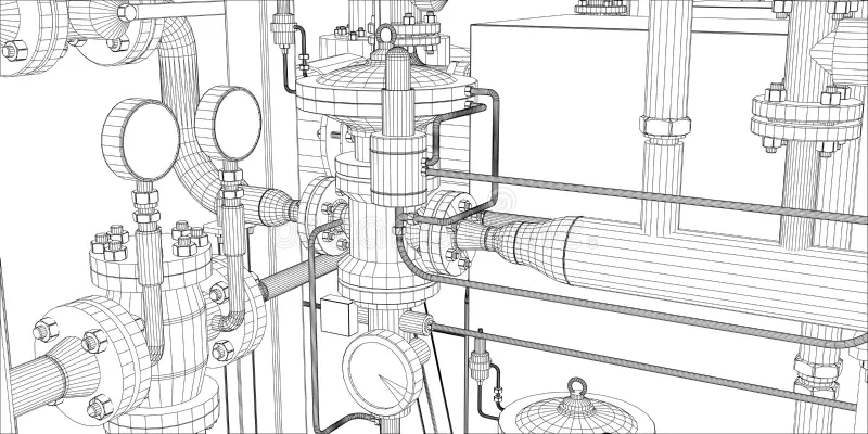
Detailed design is a critical phase in the product development and manufacturing process, focusing on the creation of comprehensive technical drawings and documentation that guide the fabrication, assembly, and quality assurance of parts and assemblies.
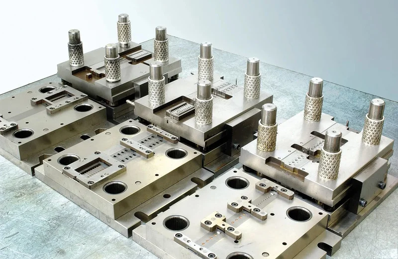
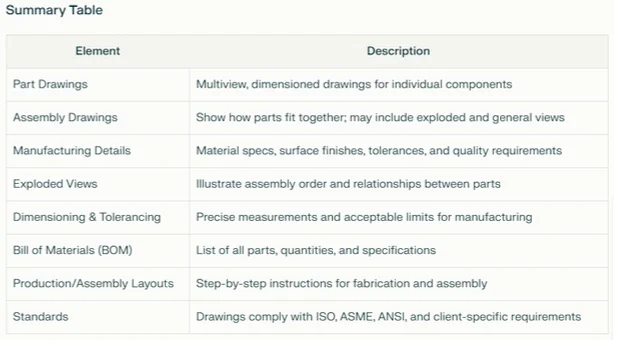
Part and Assembly Drawings:
Detailed drawings are created for each individual part, providing multiview representations with all necessary dimensions, tolerances, materials, and finish specifications. Assembly drawings illustrate how parts fit and work together, showing relationships, assembly sequences, and overall structure.
Manufacturing Details and Quality Standards:
Drawings specify manufacturing requirements, including material types, surface finishes, and critical tolerances. Adherence to recognized standards such as ISO, ASME, and ANSI ensures uniformity, quality, and global compatibility.
Exploded Views:
Exploded assembly drawings display components separated from one another, clarifying the assembly order and relationships between parts. These views are especially valuable for complex assemblies, maintenance, and repair instructions.
Dimensioning and Tolerancing:
Every drawing includes precise dimensions and associated tolerances for all critical features. This information is essential for manufacturing accuracy and quality control, ensuring that each part meets design specifications and functions correctly within the assembly.
Bill of Materials (BOM):
A BOM accompanies assembly drawings, listing all components, part numbers, quantities, materials, and relevant specifications. This document streamlines procurement, inventory management, and assembly operations.
Production and Assembly Layout Drawings:
Production drawings provide step-by-step instructions for fabrication, while assembly layout drawings guide the correct placement and connection of parts during assembly. These documents are structured and annotated according to industry and client-specific standards for clarity and consistency.
Standards Compliance:
Detailed design drawings are created in accordance with established standards such as ISO, ASME Y14, and ANSI. These standards define drawing formats, symbols, dimensioning practices, and documentation requirements, ensuring clear communication and interoperability across industries and geographies.
Clarity and Accuracy:
Drawings must be unambiguous, with clear labeling, leader lines, and part identification. Exploded and orthogonal views, section cuts, and detailed annotations help eliminate misunderstandings and reduce errors during manufacturing and assembly.

Detailed design documentation ensures that every stakeholder-from machinists to assemblers-has the precise information needed to manufacture, assemble, and verify the product to the highest standards of quality and efficiency.

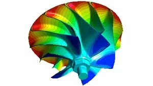
Engineering analysis encompasses a suite of advanced simulation and modeling techniques to evaluate and optimize the performance, safety, and reliability of products and systems across industries. Key methods include finite element modeling and analysis (FEM/FEA), computational fluid dynamics (CFD), and multi-body dynamics (MBD), each addressing specific engineering challenges.
Multi-Body Dynamics (MBD), Kinematic and Dynamic Analysis

Engineering analysis is fundamental to modern design, enabling virtual testing and optimization across a broad spectrum of industries, from aerospace and automotive to energy, electronics, and biomedical engineering.

We specialize in the design and development of a wide range of tooling solutions, including jigs, fixtures, precision injection molds, press tools, patterns, and dies, utilising the latest concepts and technologies. Our capabilities extend across single cavity, multi-cavity, and family molds, and we have significant experience working with a variety of plastics and complex assemblies.
By integrating advanced design tools, deep industry expertise, and a commitment to quality, we deliver tooling solutions that enhance productivity, accuracy, and efficiency across a range of manufacturing sectors.

Advantage Engineering has a proven track record in executing value engineering projects that deliver measurable results in cost optimization, weight reduction, topology optimization, and parts optimization. Through a systematic and creative engineering approach, value engineering ensures that customers receive optimal functionality at the lowest possible cost-often by identifying alternative materials, simplifying designs, and streamlining manufacturing processes.
By integrating these strategies, Advantage Engineering delivers enhanced value, improved product performance, and a competitive edge for our clients across diverse industries.